

Introduction
A warehouse AMR does not have one “navigation sensor.” It has a stack of sensors with different jobs estimate pose, see obstacles, enforce safety zones, measure wheel motion, identify inventory and confirm precise docking. Mixing those roles is one reason sensor articles become vague.
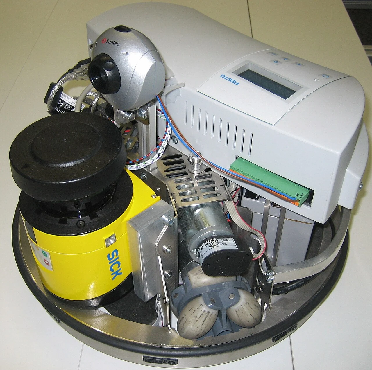
MiR250 is a useful concrete example. Its official specification lists two SICK safety laser scanners at the front and rear for 360-degree protection and two 3D cameras for pallet and obstacle detection. Those sensors complement one another; the cameras do not replace the safety scanners, and the safety scanners are not the entire localization stack.
Key findings
- Safety-rated laser scanners and perception LiDAR can look similar but have different certification, diagnostics and system roles.
- 3D cameras help detect pallets, forks, overhangs and objects outside a planar scanner field, but lighting, reflective surfaces and occlusion still matter.
- Wheel encoders and IMUs provide high-rate motion estimates but drift; external geometry or markers correct accumulated error.
- Inventory identification may use barcode, QR, RFID or cameras and is separate from collision avoidance.
- Sensor redundancy only improves safety if the system architecture defines what happens when signals disagree or a sensor becomes unavailable.
Warehouse robot sensor stack by job
| Sensor/function | Typical job | Important limitation |
|---|---|---|
| Safety laser scanner | Protective fields, safe stop/speed | Planar coverage and occlusion |
| LiDAR | Localization, mapping, obstacle geometry | Feature quality, reflectivity, contamination |
| 3D/depth camera | Pallets, elevated obstacles, object geometry | Lighting, transparency, occlusion |
| Encoders + IMU | High-rate odometry/motion estimate | Drift and wheel slip |
| Barcode/QR/RFID | Inventory/location identity | Read quality and false association |
Separate localization, perception and safety before choosing hardware
Localization answers “where am I?” Obstacle perception answers “what is around me?” Functional safety answers “must I slow or stop to keep risk within the validated limits?” Inventory sensing answers “which item or location is this?” A single camera or LiDAR may contribute to several tasks, but its safety rating and failure diagnostics determine whether it can be trusted for a protective function.
This distinction prevents a common mistake assuming a robot with impressive 3D perception automatically satisfies the safety function needed for people sharing the aisle.
LiDAR and safety laser scanners
LiDAR measures range by sending laser light and timing or otherwise estimating the return. A mobile robot can use range scans for map matching, obstacle detection and localization. A safety laser scanner is designed and certified for protective functions, with monitored fields and safety outputs integrated into the robot safety architecture.
MiR lists two front/rear SICK nanoScan3 safety scanners on the MiR250, providing 360-degree protective coverage. The important design question is scanner placement pallet overhang, forks, low objects and elevated obstacles can sit outside a single horizontal plane.
3D cameras fill the vertical blind spots
Depth cameras provide a three-dimensional point representation useful for pallets, rack geometry and obstacles above or below a planar laser. MiR250 lists two 3D cameras with a defined field of view for pallet and obstacle detection.
Camera performance changes with lighting, transparent or reflective materials, dark surfaces, dust and occlusion. Test the actual shrink wrap, black plastic, metal racks and floor reflections in the facility rather than relying on a clean demo environment.
Encoders and IMUs fast motion estimates with drift
Wheel encoders estimate distance from wheel rotation. An IMU measures angular velocity and acceleration. Combined, they give a fast local motion estimate between map updates, but slip, wheel wear and uneven flooring create error.
Warehouses with ramps, polished floors or debris should test odometry under the heaviest expected load. A localization stack must detect when predicted motion and external observations diverge rather than silently accumulating pose error.
Proximity, bump, fork and load sensors
Ultrasonic, infrared, short-range time-of-flight and contact sensors can cover near-field gaps that larger sensors miss. Forklift-style AMRs may also use fork-height, mast, load-presence or pallet-position sensing. The exact stack depends on the load-handling mechanism.
For docking, a local sensor or marker can be more useful than a globally accurate map. The robot may know its position to centimeters in the aisle but need a tighter final alignment to transfer a pallet or mate with a conveyor.
Inventory sensing is another layer
Barcode scanners, QR readers, RFID and cameras connect movement to inventory identity. An inventory-scanning robot may use high-resolution cameras or RFID antennas while its base uses a separate navigation and safety stack.
The business failure mode is different a navigation error can stop or collide; an identification error can silently corrupt stock records. Measure read rate, false associations and recovery workflow separately from driving performance.
Design the stack around failure, not sensor count
Ask what the robot does if a camera is blinded, a scanner window is dirty, an encoder fails, a localization confidence score drops or a payload blocks a field of view. A safe degraded mode may reduce speed, stop, request human assistance or switch to a redundant reference.
Sensor fusion is not magic redundancy. Two algorithms built on the same obstructed camera can fail together. True robustness comes from diversity of sensing, diagnostics and an explicit state machine for degraded operation.
Limitations and missing information
- Product specifications, software capabilities, prices and availability can change; verify the exact configuration before procurement.
- A successful vendor demonstration does not establish production uptime, intervention rate or performance in a different facility.
- Safety guidance here is educational and does not replace a site-specific risk assessment, integrator validation or applicable regulations.
Conclusion
The best warehouse robot sensor stack is the one that assigns clear responsibilities to localization, perception, safety and inventory sensing, then proves how the robot behaves when each layer becomes uncertain.
Frequently asked questions
What sensors do warehouse robots use?
Common sensors include LiDAR, safety laser scanners, 2D/3D cameras, wheel encoders, IMUs, proximity sensors, bump/contact sensors and application-specific barcode, QR or RFID readers.
Is LiDAR the same as a safety laser scanner?
No. Both can measure distance with laser light, but a safety scanner is designed and certified for safety functions with monitored protective fields and diagnostics. A perception LiDAR is not automatically safety-rated.
Why do AMRs use cameras and LiDAR together?
They provide complementary information. LiDAR gives reliable range geometry in a plane or 3D scan, while cameras can add vertical structure, texture, object recognition and pallet details.
Do wheel encoders provide enough localization for a warehouse robot?
Usually not by themselves. Encoder odometry drifts because of slip, wheel wear and floor variation. It is normally corrected using environmental features, markers or other localization references.
What sensors do inventory robots use?
Inventory robots can combine navigation sensors with barcode/QR cameras, RFID readers or high-resolution vision systems. Inventory identity sensing should be evaluated separately from mobility safety.
Sources and methodology
Related TechniaHQRobot guides
Share this article
Share the current TechniaHQRobot article page.
Continue reading
Open the latest robotics reporting, Physical AI analysis and hardware notes.