
Introduction
A camera frame and a joint-state message can arrive together while describing different moments. The picture may show the gripper approaching an object. The joint message may already describe a later pose. Combining those observations creates a state that never existed on the robot.
This timing error can enter both training data and live control. A policy may then learn the wrong relationship between a visible contact and the command that caused it. Before adding more recordings, it is useful to establish what time each stream actually represents.
Capture time and arrival time
Keep the timestamp for sensor acquisition separate from the time the host receives the message. Camera exposure, internal buffering, compression and transport can all sit between them. A software timestamp written after reception cannot reconstruct an earlier acquisition time unless the relevant delay is measured.
Joint observations and gripper commands add their own timing conventions. A commanded position is a target. A measured position describes an observation. Record both with explicit units and clock domains so that later processing can distinguish intent from motion.
What UMI measures
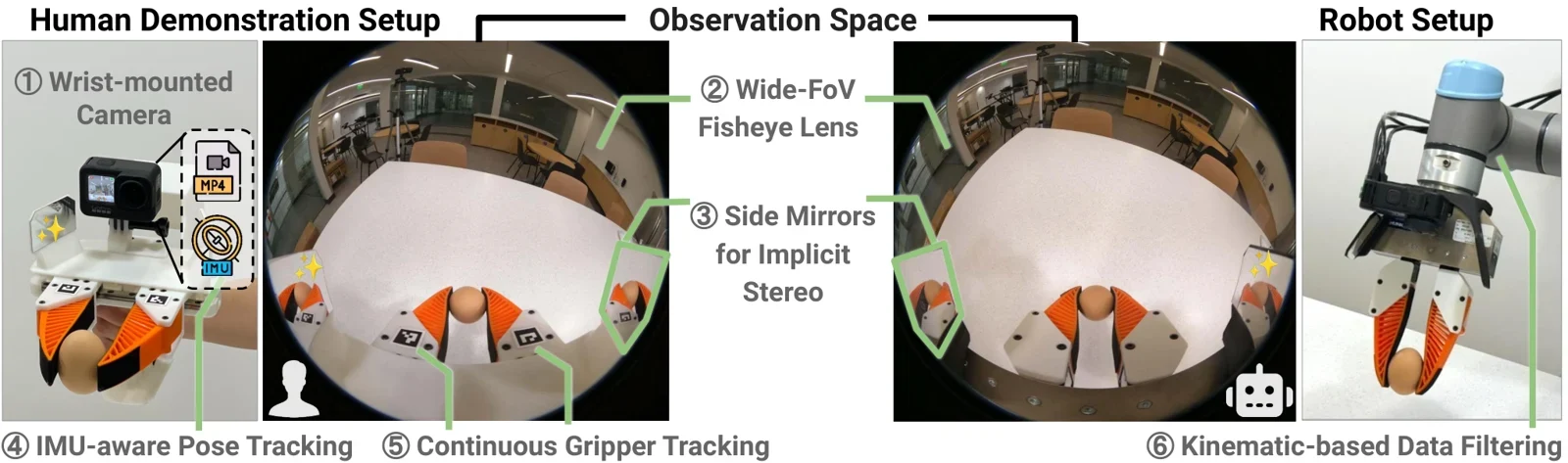
The Universal Manipulation Interface paper includes separate procedures for camera latency, proprioception latency, gripper execution latency and robot execution latency. Its policy interface accounts for inference-time delay when transferring data from handheld grippers to robot execution.
That separation is useful because one latency value cannot describe every stage of the chain. A camera replacement can change observation timing without changing actuator response. A controller update can alter execution timing while the recorded video stream remains the same. The UMI paper and implementation provide a concrete reference for studying these stages.
How a small delay becomes a spatial error
Consider an illustrative object moving at a constant 0.5 metres per second. During a 100 ms offset it travels 5 cm. At a 20 ms offset it travels 1 cm. These distances follow from speed multiplied by time. They are examples, not measurements from a particular robot.
Rotation adds another source of mismatch. A wrist camera rotates with the arm, changing where an object appears even when the object stays still. A time offset between the image and the pose used to interpret it can therefore look like a calibration error.
This is one reason to check timing and geometry separately. Improving a static camera calibration does not remove a variable delay. Conversely, synchronized timestamps do not correct an inaccurate camera-to-robot pose estimate.
A useful timing record
For every sensor and command stream, document the clock source, timestamp unit, sampling rate, sequence identifier and expected buffering. Preserve missing frames and time discontinuities in a quality report. Silently filling gaps can hide the conditions that later cause a policy to hesitate or miss a contact.
A timing check should compare repeated events visible in the relevant streams. Review the estimated offset over the whole recording, rather than measuring it once at startup. Drift and occasional buffering spikes can produce errors that a single average conceals.
Store the synchronization method alongside the dataset version. A future reader should be able to tell whether alignment used hardware triggers, a common clock, recorded timing markers or a measured software offset. State the remaining uncertainty instead of labelling every aligned sample exact.
Check again during execution
After preprocessing, confirm that the live runtime uses the same observation and action conventions as training. Queue depth, video processing and remote inference can change after deployment. A correct offline dataset does not establish the age of a command arriving at a motor controller.
Measure distributions across representative operating conditions. Record the camera exposure-to-policy delay and the observation-to-execution delay separately. Include the upper tail and the number of stale samples rejected by the runtime.
For a humanoid, keep the low-level balance loop's timing requirements separate from those of a camera-based manipulation policy. Each controller should consume observations under its own defined age limits. Changes to sensors, firmware or buffering should trigger a new timing check before comparing task performance.
Sources and methodology
Engineering analysis informed by the linked UMI work. The distance examples assume constant linear speed. They are calculations supplied to explain timing error.
Share this article
Share the current TechniaHQRobot article page.
Continue reading
Open the latest robotics reporting, Physical AI analysis and hardware notes.