

Introduction
Visual SLAM estimates robot motion from camera images. LiDAR SLAM estimates motion and builds maps from laser range measurements. Neither is universally more accurate. Cameras provide rich appearance and can be inexpensive, but depend on light, texture, calibration and motion blur. LiDAR measures geometry directly and works in darkness, yet glass, fog, dust, sparse geometry and moving objects can still degrade returns.
The correct choice follows the environment and the robot’s failure tolerance. A warehouse AMR may use a 2D safety LiDAR for localization and obstacle detection. A drone benefits from low-mass cameras and an IMU. A service robot may combine RGB-D vision, wheel odometry and LiDAR. This guide compares the sensing physics, algorithms and practical failure modes using ORB-SLAM3, RTAB-Map, Cartographer, SLAM Toolbox and Nav2 as concrete references.
Key findings
- Visual SLAM needs stable visual features or depth information; blank walls, glare and darkness can cause tracking loss.
- LiDAR SLAM measures range directly but can struggle with glass, mirrors, weather particles and repetitive geometry.
- An IMU and wheel odometry improve short-term motion estimation but introduce their own bias and slip errors.
- Loop closure reduces accumulated drift only when the system recognizes a previously visited place correctly.
- Production robots often fuse modalities because camera and LiDAR weaknesses are different rather than identical.
Visual SLAM and LiDAR SLAM compared
Performance depends on the exact camera, lens, LiDAR, environment, motion and algorithm configuration.
| Condition | Visual SLAM | LiDAR SLAM | Practical response |
|---|---|---|---|
| Low light or darkness | Monocular and stereo cameras degrade unless illumination or active depth is available | Active laser ranging generally remains usable | Fuse LiDAR/IMU or add controlled illumination |
| Textureless walls | Few stable image features | Geometry may remain observable if surfaces create distinct ranges | Use depth, LiDAR or artificial landmarks |
| Glass and mirrors | Reflections and transparency confuse appearance and depth cameras | Returns can pass through, reflect or disappear | Use sensor fusion and conservative obstacle policies |
| Dust, fog or rain | Image contrast drops and lenses become contaminated | Particles create noisy or false returns | Protect sensors, detect degradation and reduce speed |
| Large open space | Scale and features can weaken, especially monocular vision | Long-range LiDAR can preserve geometry within sensor range | Fuse GNSS outdoors or add landmarks |
| Compute load | Feature extraction, tracking and dense reconstruction can be heavy | 3D point-cloud registration can also be heavy | Match algorithm and map resolution to compute budget |
A sensor specification alone does not determine localization quality.
What SLAM actually estimates
Simultaneous localization and mapping estimates the robot pose while constructing or updating a representation of the environment. Pose includes position and orientation. The map can be a 2D occupancy grid, sparse visual landmarks, a 3D point cloud, a voxel structure or a semantic representation. The robot never observes its true pose directly. It combines imperfect sensor measurements with a motion model and updates uncertainty over time.
Localization can continue against a previously saved map after mapping is complete. That distinction matters in production. A warehouse robot may create a map during commissioning, then localize within it every shift. A research robot may keep extending the map online. Mapping, localization and navigation are connected but separate Nav2 consumes pose and map information to plan and control motion; it is not itself a SLAM sensor.
How visual SLAM works
Feature-based visual SLAM detects repeatable image points, describes them and matches them across frames. Camera geometry estimates motion from those correspondences. ORB-SLAM3 supports monocular, stereo and RGB-D configurations and can incorporate inertial measurements. Pure monocular image geometry recovers structure and motion only up to an unknown scale; camera motion alone does not supply metric scale. Additional metric information is needed, such as known geometry or calibrated inertial measurements with successful initialization and sufficient motion. Stereo and RGB-D cameras provide depth under supported conditions.
Direct methods instead use image intensity over larger regions. Both families depend on calibration, timestamp alignment and suitable motion. Fast turns create blur. Automatic exposure can change appearance. Rolling-shutter cameras distort geometry during motion. Visual-inertial odometry improves short-term tracking by integrating angular velocity and acceleration, but IMU bias must be estimated. A camera with high resolution is not automatically better if it increases latency or produces blurred frames.
How LiDAR SLAM works
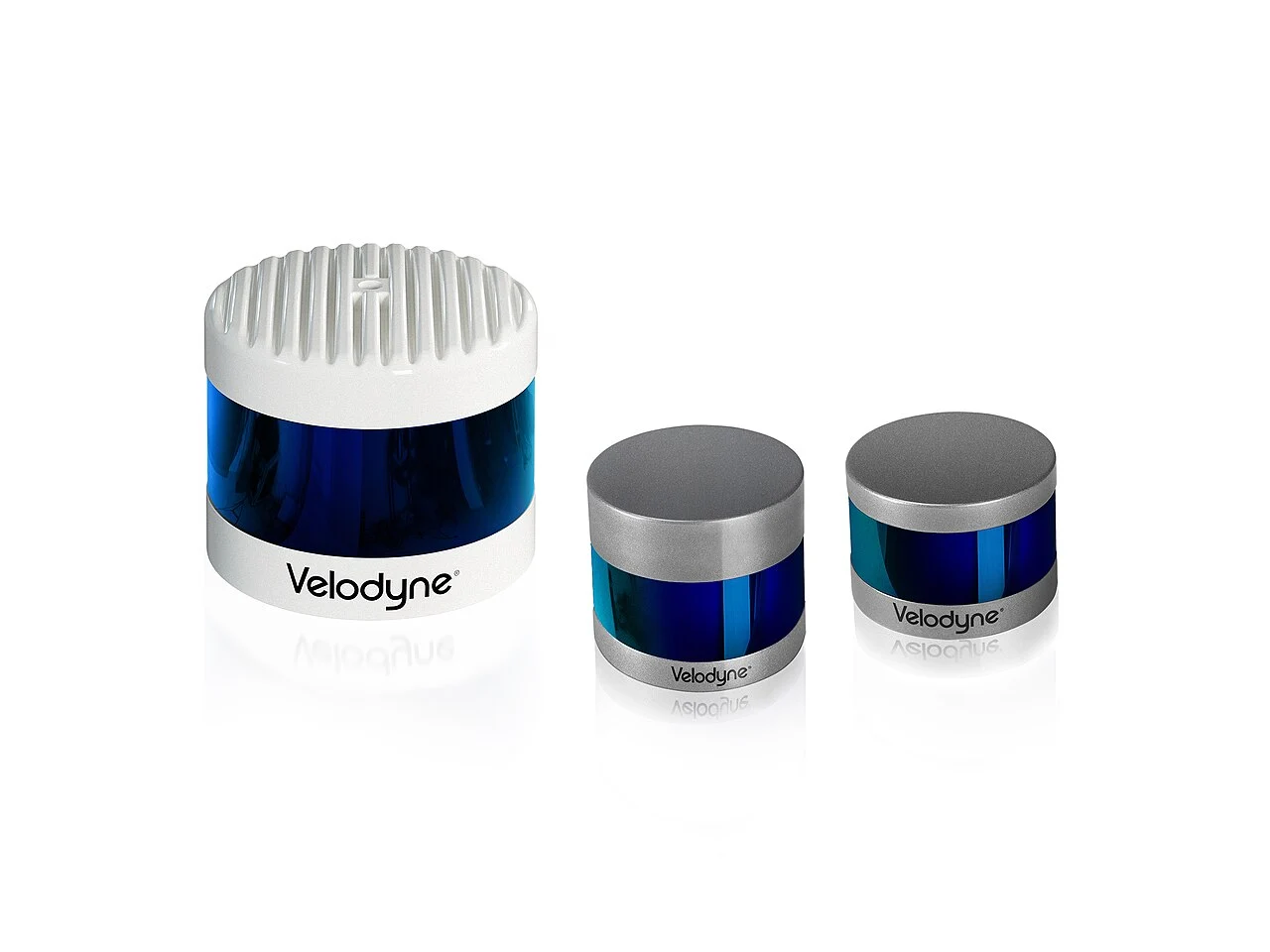
LiDAR SLAM aligns successive range scans or point clouds and combines them with odometry or inertial data. A 2D LiDAR observes one plane and works well for indoor floor layouts where walls, racks and posts intersect that plane. SLAM Toolbox provides ROS 2 mapping and localization workflows around 2D laser data. Google Cartographer supports 2D and 3D trajectories with sensor fusion and scan matching.
A 3D LiDAR captures richer geometry for uneven terrain, ramps and outdoor environments, but point-cloud processing and data rates are higher. Scan matching can become ambiguous in long identical corridors or open spaces with little structure. Motion distortion occurs because a spinning LiDAR acquires points over time while the robot moves. Accurate timestamps and IMU compensation become critical on fast platforms.
Accuracy is a system result
It is misleading to assign one accuracy number to visual or LiDAR SLAM. Error depends on sensor noise, calibration, field of view, feature distribution, speed, map scale and loop closures. A high-quality stereo camera in a textured, well-lit laboratory can outperform a low-cost sparse LiDAR. A stable 2D LiDAR in a structured warehouse can outperform a camera pointed at repeating white walls. Benchmark results do not transfer automatically between environments.
Evaluate both local and global error. Local consistency determines whether the robot can pass through a doorway or dock. Global drift determines whether a long loop closes correctly. A map can look visually clean while its coordinate frame is distorted. Use ground truth from motion capture, surveyed landmarks, fiducials or a higher-grade reference when possible. For production, measure repeat docking and route completion rather than only average trajectory error.
Lighting, texture and visual failure
Visual SLAM relies on observable changes in images. Darkness removes signal. Sun glare clips pixels. Repeating floor patterns create ambiguous matches. Textureless walls provide few features. Dynamic crowds can dominate the image with points that do not belong to the static world. RGB-D cameras using structured light or active infrared can lose depth outdoors when sunlight overwhelms the projector.
Mitigation includes global-shutter cameras, wider dynamic range, controlled lighting, multiple fields of view and semantic masking of moving objects. Exposure should be monitored as a health signal. A system needs a response when tracking quality falls slow down, stop, relocalize or switch to another sensor. Continuing at full speed after visual tracking is lost converts a perception limitation into a safety event.
Glass, dust and LiDAR failure
LiDAR measures returned light, so transparent and reflective surfaces are difficult. A beam can pass through glass, reflect at an unexpected angle or return weakly. Black materials can produce low intensity depending on wavelength and surface. Dust, fog, rain and spray scatter light and create transient points. A 2D scan plane can miss objects above or below it, including overhanging shelves and low obstacles.
Filtering helps but can remove real hazards if applied aggressively. Multi-echo information, intensity values, 3D sensing and cameras provide additional evidence. Sensor placement should reduce contamination and protect the window without creating blind spots. Cleaning is an operational requirement. A map made in a clean warehouse may perform poorly when shrink wrap, temporary pallets or dust alter the visible geometry.
Drift, loop closure and relocalization
Every odometry estimate accumulates error. Loop closure recognizes a previously visited place and adds a constraint that can correct the trajectory. Visual systems use appearance and geometric verification. LiDAR systems compare scan structure. False loop closures are dangerous because they can deform the map or jump the pose. Robust systems require consistency checks and may delay accepting a loop until enough evidence exists.
Relocalization is the ability to recover pose after tracking loss or startup. A robot should be tested from multiple positions, headings and changed scenes. Saving a map is not enough. Operators need a procedure for map updates and version control. Moving racks or rebuilding walls can invalidate constraints. Production fleets should know which map version each robot uses and how a rollback occurs after a bad update.
ORB-SLAM3 and RTAB-Map
ORB-SLAM3 is a research-grade open-source system for monocular, stereo, RGB-D and visual-inertial SLAM. It is influential because it demonstrates a complete feature-based pipeline with tracking, local mapping and loop closing. Integration still requires camera calibration, build management and platform-specific handling. It is not a turn-key safety-certified navigation product.
RTAB-Map focuses on real-time appearance-based mapping and supports RGB-D, stereo, LiDAR and multi-session workflows. It is commonly used with ROS for 3D mapping and loop closure. Its flexibility brings configuration complexity synchronization, database size, memory management and sensor topics must be tuned. Both tools are useful for prototyping and research, but deployment needs monitoring, recovery and maintained software versions.
Cartographer, SLAM Toolbox and Nav2
Cartographer performs graph-based 2D or 3D SLAM using scan matching and sensor fusion. It can produce strong maps but has many parameters and a learning curve. SLAM Toolbox is closely aligned with ROS 2 workflows for 2D mapping, lifelong mapping and localization. It integrates with laser scans, transforms and pose graphs. Selection should follow sensor type, community support and the team’s ability to tune and debug the package.
Nav2 uses localization, costmaps, planners, controllers and behavior trees to move a robot toward goals. It can work with AMCL on a saved map or with SLAM during mapping. A good SLAM pose does not guarantee navigation success if footprints, obstacle layers or controller limits are wrong. Testing must cover localization, planning and stopping as an end-to-end system.
When sensor fusion is preferable
A warehouse AMR often combines wheel encoders, IMU and 2D LiDAR because the floor is planar and safety scanners are already present. Cameras can add semantic object detection and barcode reading. An outdoor delivery robot benefits from cameras, GNSS, IMU and LiDAR because curbs, traffic participants and satellite visibility vary. A drone may prioritize stereo or monocular visual-inertial odometry because mass and power limit LiDAR options.
Fusion is not simply adding sensors. Extrinsic calibration defines the transform between them, time synchronization aligns measurements and an estimator assigns uncertainty. A poorly synchronized high-end LiDAR and camera can perform worse than one calibrated sensor. Design degraded modes explicitly what happens when GNSS drops, a camera is blinded or a LiDAR reports contamination? The robot should know when confidence has fallen below the level required for motion.
How to choose for a real robot
Record representative data in the target environment before committing. Include bright windows, night operation, crowds, glass, dust, long corridors, ramps and maximum speed. Run candidate algorithms offline with the same timestamps and calibration. Measure pose error, CPU and GPU load, memory, startup time, relocalization and failure duration. Then test on the robot with stopping and recovery behavior enabled.
Cost should include integration and maintenance, not only sensor price. Cameras need lenses, mounts and lighting. LiDAR needs protective placement and may be expensive to replace. Compute, calibration tools and engineering time can dominate the bill. Select the simplest stack that meets the required operating domain, then add redundancy where the consequence of lost localization justifies it.
Limitations and missing information
- Algorithm performance depends on calibration, timestamps and tuning; default parameters are not a universal baseline.
- Open-source SLAM packages are not automatically safety-certified products.
- Glass, weather, crowds and changing layouts can break assumptions made during laboratory testing.
- Published benchmark accuracy may not predict docking or navigation performance in the target facility.
- Sensor fusion adds calibration and failure-management complexity as well as redundancy.
Conclusion
Visual SLAM is attractive when cameras already serve perception and the environment provides light and texture. LiDAR SLAM offers direct geometry and strong indoor performance, including darkness, but has its own reflective-surface and weather failures. Most production robots should choose from recorded target-environment evidence. A fused camera, LiDAR, IMU and odometry stack is justified only when each modality has a defined role and degraded mode.
Frequently asked questions
Is LiDAR SLAM more accurate than visual SLAM?
Not universally. Accuracy depends on the sensor, environment, motion, calibration and algorithm. LiDAR is often strong in structured geometry; vision can be strong in textured scenes.
Can visual SLAM work in the dark?
A passive camera needs light. Active RGB-D sensors or illumination can help, but range and outdoor behavior vary. LiDAR is generally more independent of ambient light.
Why does SLAM drift?
Each pose estimate contains error. Repeated integration accumulates that error until loop closures or external references add corrective constraints.
What is the difference between SLAM Toolbox and Nav2?
SLAM Toolbox builds or localizes against a 2D map. Nav2 plans and controls robot motion using localization and costmap information.
Should an AMR use both cameras and LiDAR?
Often yes when cameras add semantics and LiDAR provides geometry, but fusion must be calibrated, synchronized and tested. More sensors do not guarantee a better system.
Sources and methodology
Evidence for Visual SLAM vs LiDAR SLAM was rechecked on July 23, 2026 against UZ-SLAMLab, IntRoLab, Google Cartographer. Time-sensitive prices, permits, service areas and certifications stay dated, and a missing supplier value is not converted into an official specification.
Related TechniaHQRobot guides
Share this article
Share the current TechniaHQRobot article page.
Continue reading
Open the latest robotics reporting, Physical AI analysis and hardware notes.